Published: Jan 3, 2020 by K. E. Claytor
This project started out as an LED clock for my kid, but quickly evolved into just a cool interactive light-show that they could enjoy (know your audience - the clock function was not a killer feature).
Here’s the summary video:
In addition to the twelve RGB LEDs, the three buttons allow for eight modes of operation and the “soft-pot” touch potentiometer allows for continuous selection, and selections that can be mapped to the clock face.
This project also appears at:
Hardware
The electronics parts list consist of:
- Trinket M0
- 12x 8 mm NeoPixel LEDs
- 3x latching LED pushbuttons
- Soft-pot touch potentiometer
- Mini protoboard
- 3x 220 Ohm resistors
- 1x 10k Ohm resistor
- 1x 10 uF capacitor
- USB (A to micro) cable
The non-electronics parts consist of:
- 1/4” plywood “face”
- cardboard
- paint
- glue
Assembly
Cut the plywood into a circle and drill twelve 8mm (x”) holes in a circle pattern. The LEDs can be press-fit in and then soldered together. Drill a series of 2mm holes and connect them to feed the soft-pot leads through. Glue the cardboard around the plywood, then cut three holds for the buttons.
Wiring
I’ll introduce the full circuit diagram and then break it down. First the wiring schematic:
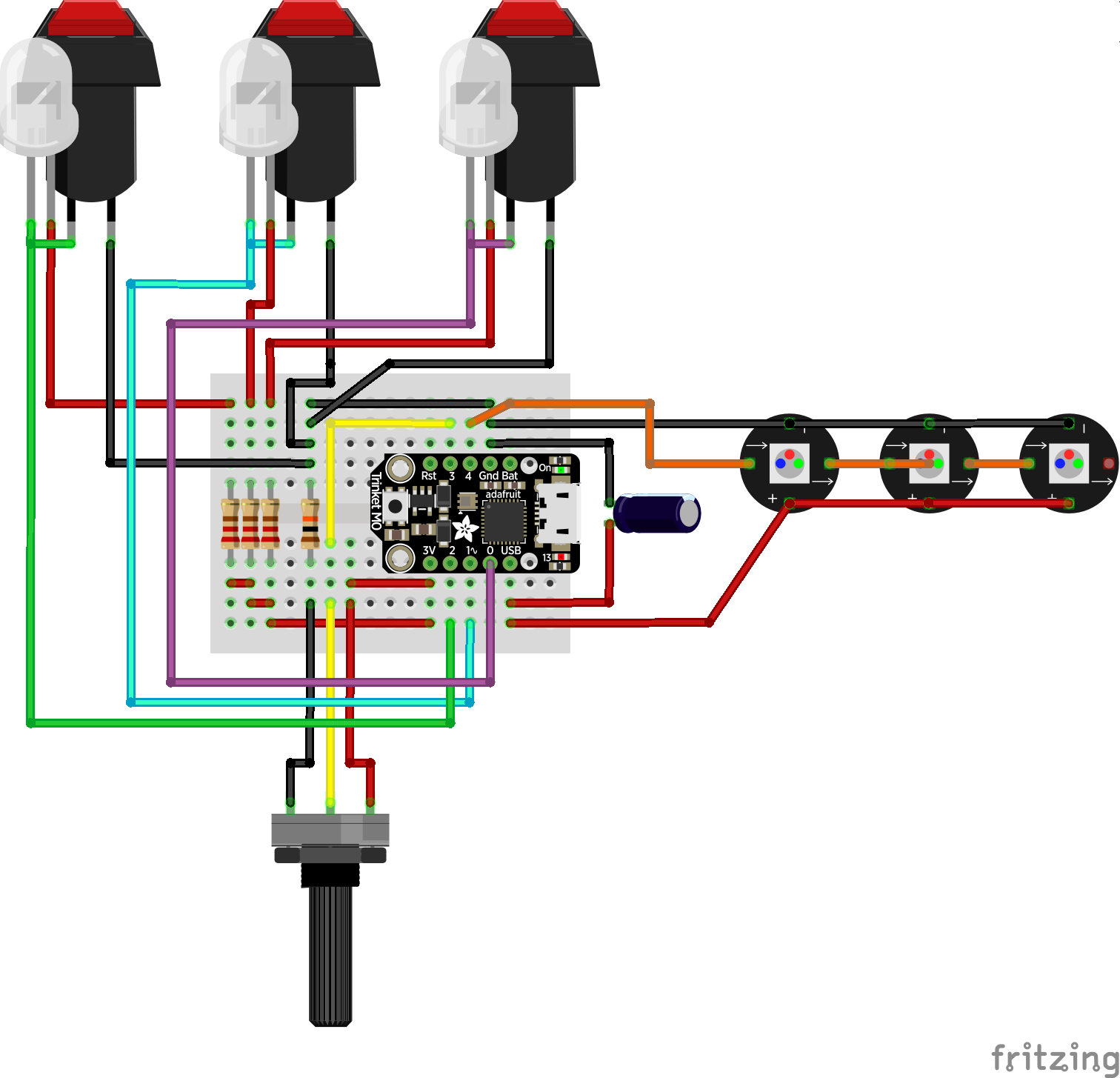
And the circuit diagram:
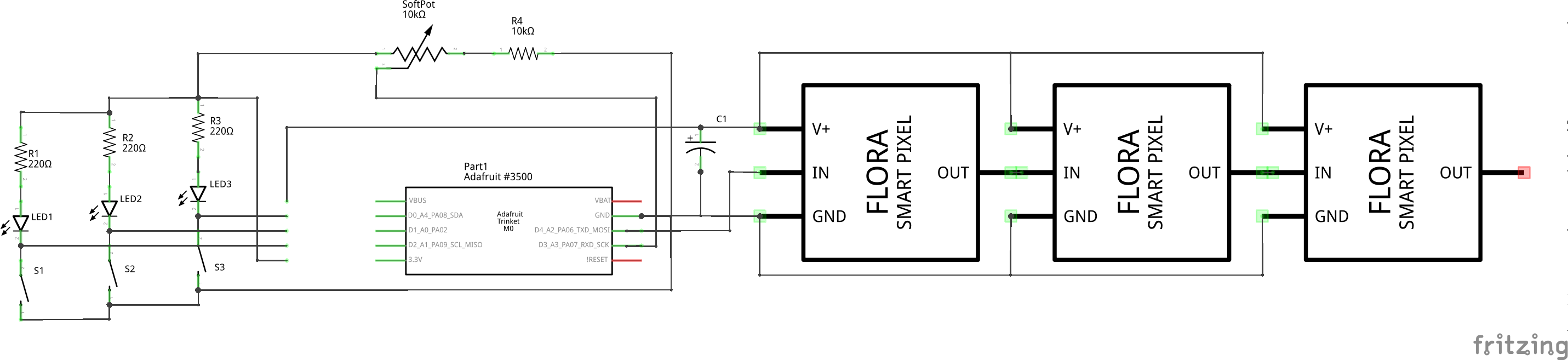
The individual NeoPixels are all connected. The cathodes (- terminal) and anodes (+ terminal) are all solidered together. Since they don’t have any capacitors built in, and each nominally needs a 100nF capacitor (see the NeoPixel uberguide, we can add the capacitance and use a 1-10 uF capacitor between the V USB (5 V) and ground pins on the Trinket. The data out from each NeoPixel is then connected to the data in of the next until the last pixel is reached. The first data is the connected to digital pin 3 on the Trinket.
The soft-pot is nominally a 0-10 kOhm resistor, with a variable resistance depending on where it is touched. We us a 10 kOhm resistor as suggested in the data sheet. This shifts the touch range from ½ Vcc (1.8 V) to Vcc (3.2 V), and allows us to detect when there is no touch (when the sense voltage is less than 1.8 Vcc). Unfortunately, I have noticed that when touch is removed the output voltage can fluctuate.
Here’s an image of the wiring with just the LEDs and the soft-pot:
The buttons include an internal LED, which can be illuminated independently of the state of the button. However, the Trinket is pretty low on input / output pins (this project uses all of them), and so I wired the LED in series with the latching button itself. This way, when the button is pressed, the LED is lit.
In general the buttons can be wired in one of two ways. In the “pull up” mode, when the switch is closed, sense output (the connection to the microcontroller) is pulled up to Vcc. This requires that the pin in the microcontroller is put in “pull down” mode - ie an internal resistor connects that pin to ground. Here’s a small schematic:
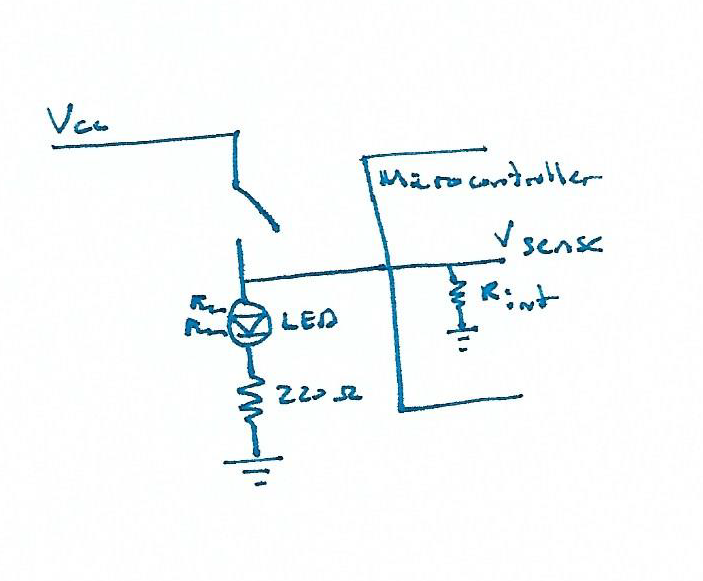
One advantage of this is that then when you read that pin in code, if the value is high the pin is being depressed. One disadvantage is that if there is any other resistance in series with the internal resistor, you might not get a full digital on signal.
Initially I did it this way, but noticed that I was only getting a signal that fluctuated between 0.5 V and 1.2 V (you can test this by switching the pin to an analog input and reading the voltage). In the schematic above, there should be no resistance in series with the microcontroller pin’s internal resistor. However, when I wired this, I think I put the microcontroller connection between the LED and the 220 Ohm resistor, meaning the internal LED resistance was in series, giving me the lower voltage.
The second way is doing a “pull down” switch. In this mode, the switch shorts the microcontroller pin to ground. On the microcontroller side the pin is “pulled up” with an internal resistor so that it naturally reads digital high. The schematic looks similar, but with the parts inverted;
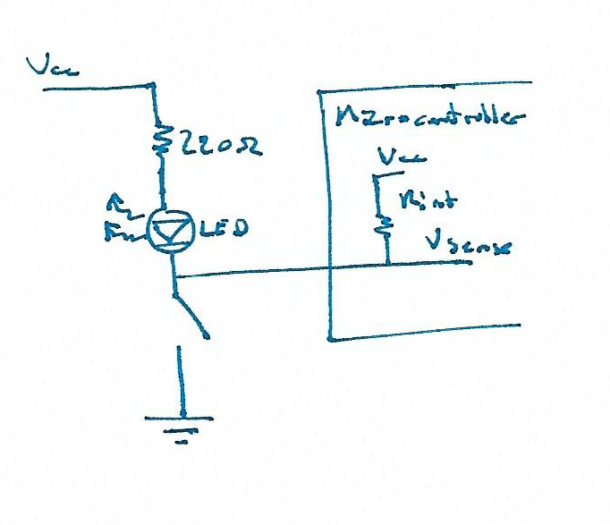
The advantages of this are that it’s really easy to short the pin to ground (you don’t have to worry about damaging anything). The disadvantage is that the button is depressed when the pin is digital low, so you have to invert the pin state in code.
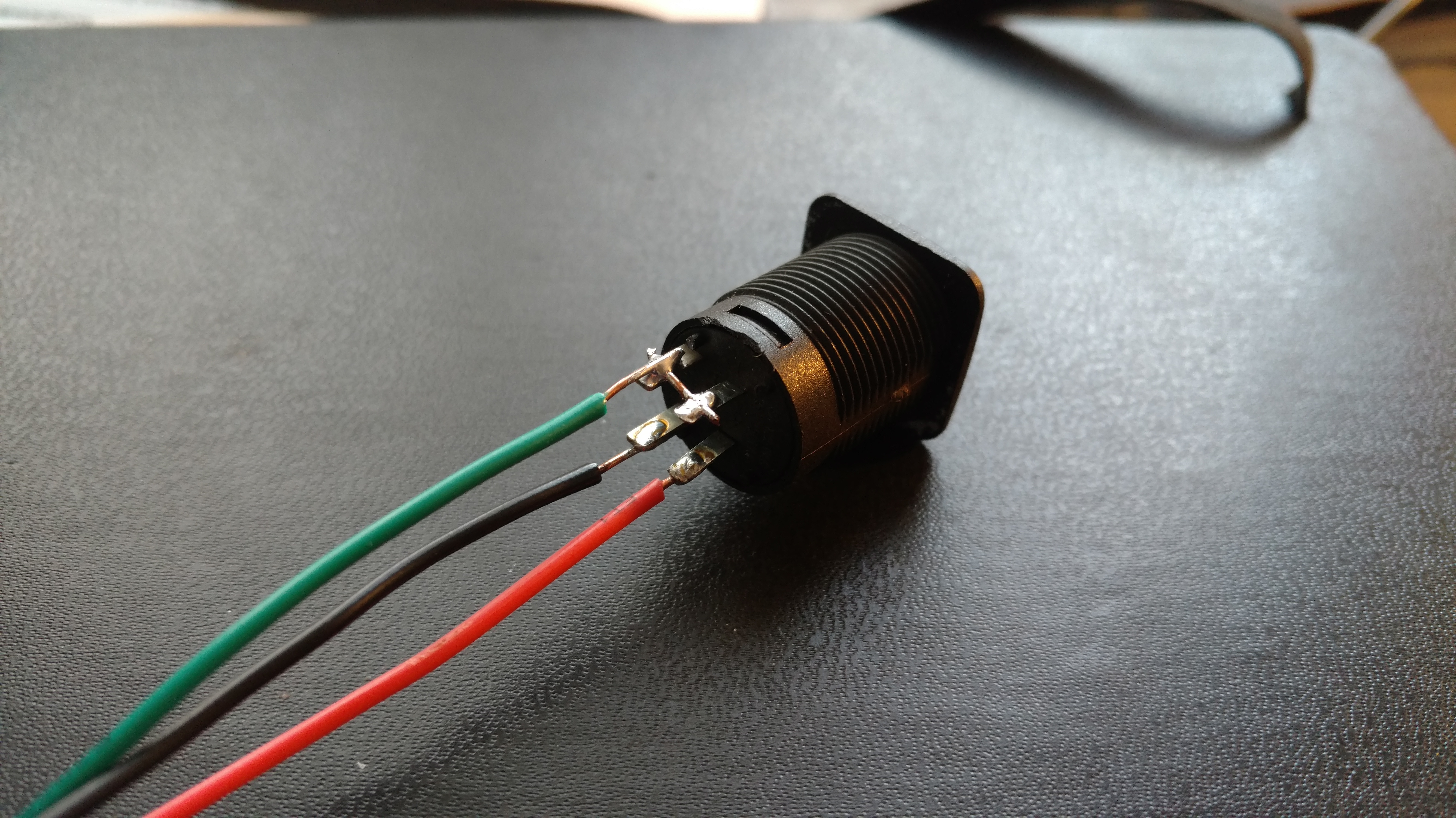
When using either of the above schematics, you only need three wires coming out of the button - you can jumper one of the LED leads to the switch:
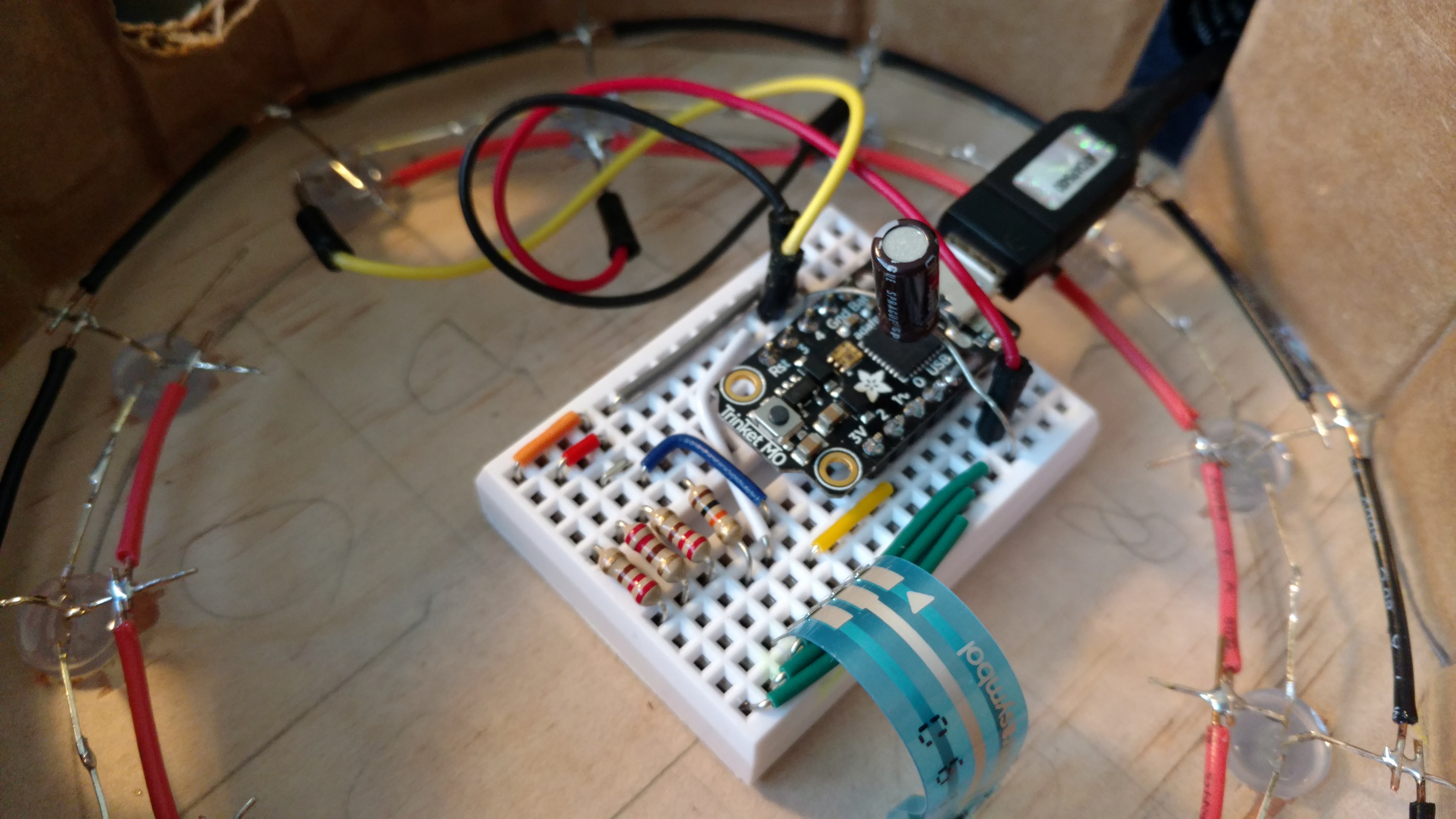
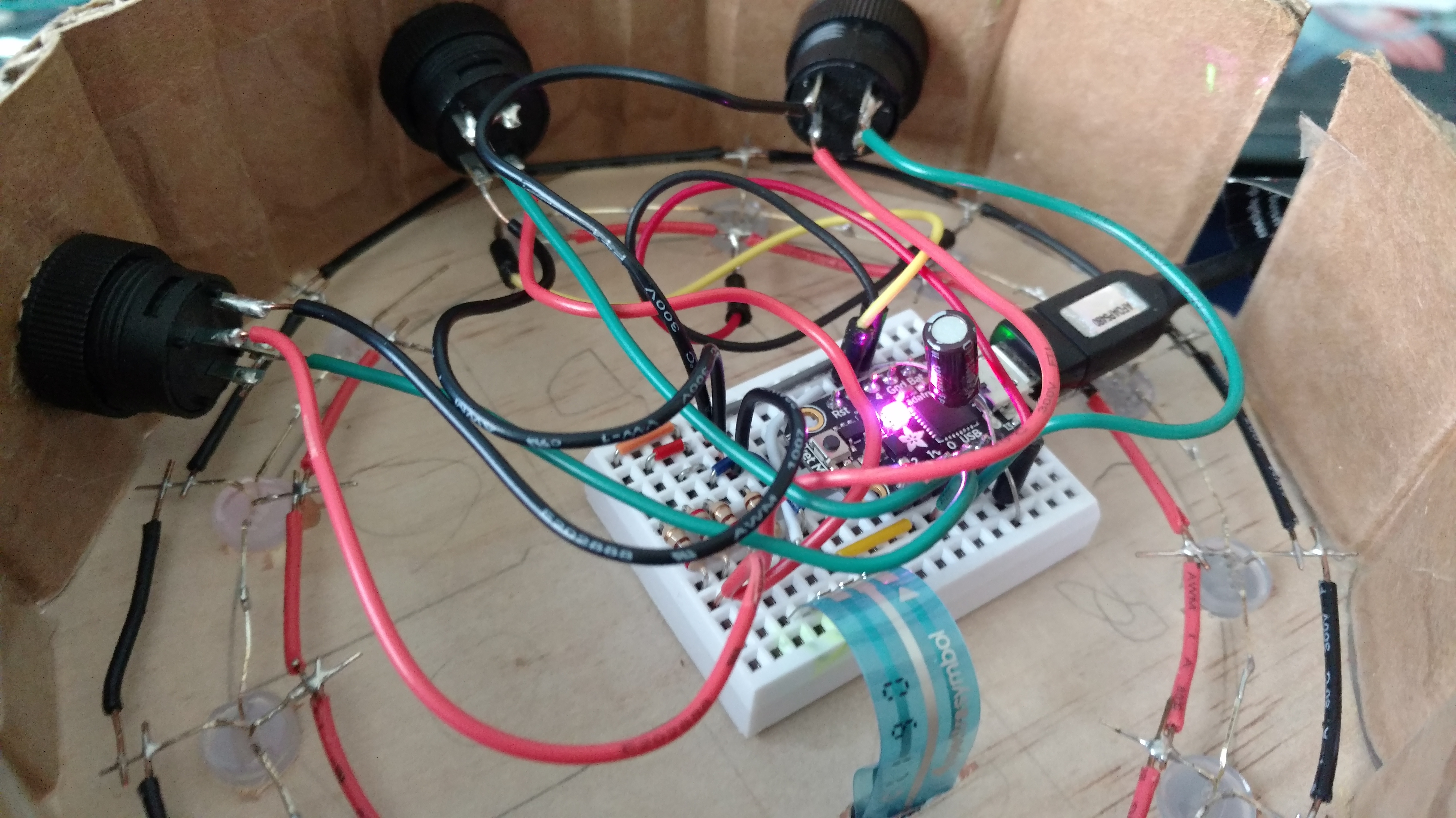
Here’s the fully wired interior:
Code
The code can be split into; 1) the button logic, 2) the LED display logic, and 3) the soft-pot interaction logic.
For the buttons, we create three digital inputs using the internal pull up resistors:
import digitalio

# Red Button
button_r = digitalio.DigitalInOut(board.D2)
button_r.switch_to_input(pull=digitalio.Pull.UP)
Next we create a function that reads the button state, doing the appropriate inversion for when the button is pressed and returns a tuple of the state of the three buttons:
def get_button_state():
    """ Read and return a tuple of which buttons are pressed.

    returns:
        (Red Pressed, White Pressed, Green Pressed)
    """
    buttons = [button_r, button_w, button_g]
    state = tuple(not b.value for b in buttons)
    return state
Finally, we switch our action / mode logic based on which buttons are pressed.
while True:
    if buttons == (False, False, False):
        print("Lights off")
        ...
    elif buttons == (True, False, False):
        print("Red button pressed")
        ...
    elif buttons == (False, True, False):
        print("White button pressed")
        ...
    elif buttons == (False, False, True):
        print("Green button pressed")
        ...
    elif buttons == (True, False, True):
        print("Red+Green = Follow mode")
        ...
    elif buttons == (True, True, False):
        print("Red+White = Rainbow wheel")
        ...
    elif buttons == (False, True, True):
        print("White+Green = Rainbow picker")
        ...
    elif buttons == (True, True, True):
        print("Red+White+Green = Rainbow fade")
        ...
    time.sleep(0.1)
The NeoPixel driver library is very simple to use, just create a pixel object on the digital output pin the pixels are connected to;
import neopixel

# NeoPixel strip (of 16 LEDs) connected on D4
NUMPIXELS = 12
BRIGHTNESS = 0.2
ORDER = neopixel.GRB
pixels = neopixel.NeoPixel(board.D4, NUMPIXELS, brightness=BRIGHTNESS, auto_write=False)
Then you can change the colors on a per-pixel basis. Here we have told the pixels to not auto-show - ie do not update the pixel colors until the .show() method is called:
# Initalize pixels OFF
for i in range(NUMPIXELS):
    pixels[i] = OFF
pixels.show()
Most of the pixel logic from here on out is just fancy manipulation of the colors.
Finally, there is the soft-pot logic.
Here we use an analog input to read the voltage across the third terminal.
If the voltage is less than 1.8 V then there is no touch and we return None.
This allows us to test later if there is a touch with if voltage:.
If there is a touch, it reads between 1.8 V and 3.2 V, we just map that to a new range (eg; 0-1, or 0-12 (12 pixels), or 0-255):
def voltage_to_int(voltage, int_max):
    """ Translate the circular touch pad to an integer range.

    NOTE: If the voltage is below TOUCH_MIN_V, this returns None
    """
    if voltage < TOUCH_MIN_V:
        return None
    else:
        mapped = translate(voltage, TOUCH_MIN_V, TOUCH_MAX_V, 0, int_max-1)
        mapped = (int(mapped) + int_max//2) % int_max
        return mapped
Depending on how you align the soft-pot with the “top” of the clock, you may need a fixed offset.
For mine, the touch pad was installed “upside down” so we have to shift everything by ½ of the output range.
Once I have this value, I apply the modulo operation to ensure that the value does not exceed the int_max range.
For many of the modes I’ve implemented, I map the touch range to something between 0-NUMPIXELS, which maps to “which pixel is the press near”. For the color-wheel selector, the range is mapped to the 0-255 range used in the basic adafruit color wheel demo.
Finally, when there is no touch, we may want a slowly changing demo. For this, we just implement a counter which increments with our loop. When there’s a touch, we can use the touch input, but when there’s no touch we use the counter input:
# Initialize to zero
idx = 0
while True:
    # Increment every loop
    idx += 1
    ...
    elif buttons == (True, False, False):
        print("Red button pressed")
        # If there is no press, cycle based on the loop index
        if not offset:
            offset = idx // 5
        set_three_colors(PINK, PURPLE, YELLOW, offset)
    ...
Conclusion
That’s it - a little bit of soldering and a few lines of code have a really neat clock face that we can play around with. You can use the three buttons and the LED colors to set hour, minute, second. You could also display the month, the phase of the moon, or something else that likes to count by twelves. With three buttons, this still leaves you with 5 modes to add additional interactivity, as shown above.